Charles Malleson
A novel clock design is presented featuring a cube rotating in 3D space. Two edges of a wire-frame cube are designated as the hour and minute hands of an analog clock face. The cube is continuously rotated over time so as to align these edges with the respective hands of the clock when viewed head-on. Determination of the rotation is based on principles from 3D graphics. The concept was realized in digital form as a watch face for a fitness tracker, and ultimately as a physical artwork based on an actuated gimbal designed to look like an old-fashioned ‘steampunk’ machine.
Introduction
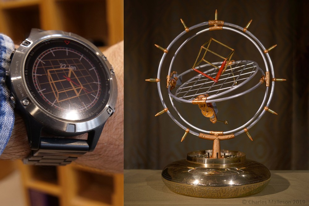
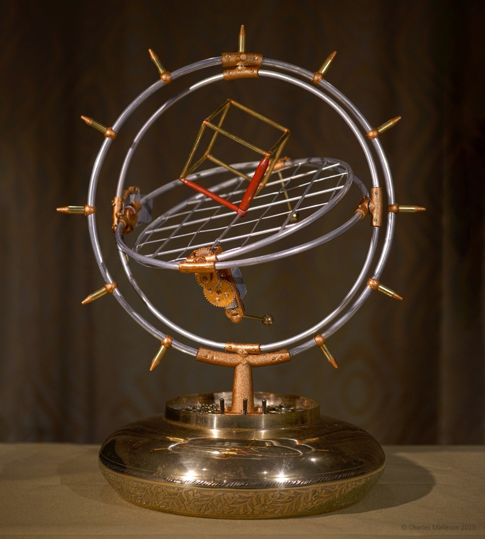
One of the simplest objects which can be rendered using 3D graphics is the humble wire-frame cube. Yet there are many ways of looking at a cube and depending on how the cube is oriented with respect to the viewer, two adjacent edges may form any angle, acute, right or obtuse. While brainstorming ideas for programming a new watch face for a personal fitness tracker, the idea of using views of a 3D cube as a watch face was arrived at: two edges of a 3D wire-frame cube are designated as the hour and minute hands of an analog clock face, respectively. Over the course of the 12-hour day, the cube is continuously rotated in 3D in such a way that the observer’s view of the cube edges coincide with the respective hands of the clock when viewed head-on. The precise rotational trajectory required to achieve this is obtained using the basic principles from 3D graphics (rigid body transforms and 3D-to-2D perspective projection) along with non-linear optimization. Following initial implementation of the concept as a custom face for a fitness tracker, a functional physical model was created using a Raspberry Pi-controlled servo-actuated gimbal. The watch face features ‘retro’ wire-frame 3D graphics, while the mechanical gimbal designed to look like an old-fashioned ‘steampunk’ [1] contraption, belying the modern electronics within that make both artifacts possible. The following sections describe the optimization of the motion trajectory of the cube, the implementation of the watch face, and the design of the mechanical gimbal cube clock, which is shown below in Figure 1.
Optimization of viewing parameters
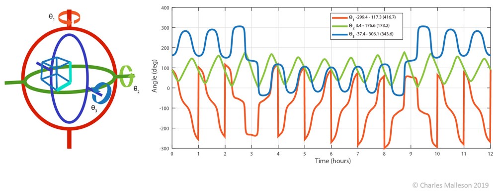
In 3D computer graphics, a 2D image of a 3D object is obtained first by applying a rigid body transform to the object (or equivalently, to the virtual camera) and then applying a projection to obtain the location of the transformed 3D points in the 2D image [2]. While there are many representations of rotation used in graphics, including rotation matrices, quaternions and Euler angles, the most suitable parametrization for the purposes of the physical realization of the cube clock is proper Euler angles [3] (θ1, θ2, θ3), which can be directly realized by the gimbal of concentric rings, each offset from its parent by 90 degrees, which is the arrangement used in mechanical gyroscopes for inertial navigation [4].
Beginning with a unit cube with origin (0,0,0), let edge (0,0,0)-(0,0,1) and (0,0,0)-(0,1,0) correspond to the hour and minute hands, respectively, with (0,0,0) corresponding to the center of rotation of the hands. The cube is mounted on the inner ring of the gimbal with the origin (0,0,0) at the center of rotation. A cost function is setup in which the difference between the three 3D cube vertices projected into the virtual camera and the respective endpoints of the 2D clock hands is minimized for a given time of day, effectively bringing the cube edges into alignment with the clock hands, which inherently ensures that the hour hand appears shorter than the minute hand [5]. By applying standard quasi-Newton numerical optimization [6], the trajectories the rotation trajectories for each minute of the 12-hour day are obtained. Figure 2 shows the rotation trajectories as optimized for the physical cube clock. Note that the rotation of the outer ring is wrapped back by 360 degrees every hour on the hour in order to allow the rotation to be achieved with the standard (limited range) servo in the physical version of the clock.
Virtual Implementation: Retro 3D Graphics on a Watch
The watch face version of the cube clock was implemented for the Garmin Fenix 5 fitness tracker. The software development kit available from the manufacturer [7] allows developers to create custom applications and watch faces for compatible wearable devices, using the ‘Monkey C’ programming language. The onboard memory and processing power of the target device are constrained and native graphics support is limited to 2D graphics (e.g. drawing lines and text). For this project, a rudimentary ‘retro’ 3D graphics rendering approach was applied in which 3D wireframe objects were drawn by projecting their vertices to 2D and drawing lines in a single color, without shading, thus avoiding the need for the complexity of a depth buffer for occlusion handling. The other elements such as the hour and minute ticks, the second hand and text for the date are drawn over the 3D scene. The vertices and edges of the 3D scene geometry, consisting of a grid for the floor along with the cube are stored in the program along with the motion trajectory lookup table containing the viewing distance and 3D rotation parameters over the 12-hour day. The edges corresponding to the hour and minute hand are drawn thicker than the other edges of the cube for improved readability. By sampling the motion trajectory in every 4 minutes and reconstructing intermediate times using cubic interpolation, the lookup table can be accommodated directly in the main program memory, which in this case is limited to just 90KB. Figure 3 shows the watch face running on the wearable device.

Physical Implementation: Mechanical Gimbal
In designing the mechanical version of the cube clock, attention was given both to function and aesthetics, with an overall aim to create a functional analog clock which has the appearance of an old-fashioned mechanical apparatus, built from metals, particularly brass and copper, reminiscent of ‘steampunk’ artwork. An old brass flower bowl turned upside down and decorated with non-functional brass gears was used as the base. The base contains the bulk of the electronics and the gimbal which actuates the cube motion is mounted on it.
Electronics
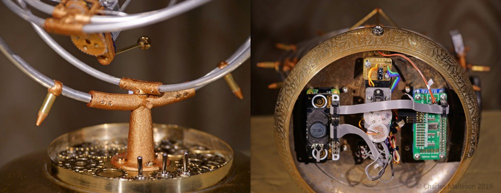
The cube clock is controlled by a Raspberry Pi Zero embedded PC running Raspbian Linux [8] and running custom Python code to implement the clock motion. Attached to the Pi are three off-the-shelf ‘hat’ add-on circuit boards, namely a servo hat, real-time clock (RTC) hat, and speaker hat. The servo hat allows the servos to be controlled using 12-bit resolution pulse width modulation (PWM), allowing for more accurate positioning of the gimbal than the built-in 8-bit PWM driver onboard the Pi. The RTC hat is required to maintain the date and time on the device when the power is switched off, since the Pi does not have a built-in RTC and the cube clock is intended to be used offline. The speaker hat adds audio output capability, allowing a sound effects to be played and status messages to be played (there is no display). In addition a light-dependent resistor is connected to the general purpose input/output (GPIO) of the Pi, which facilitates putting the clock into sleep mode (suppressing the clock motion and audio output) when the environment is dark. Finally three self-centering (on-off-on) toggle switches are connected to the GPIOs. The switches are mounted on the top of the base and are used to allow user access to adjust the time, trim the positioning of the gimbal servos and trigger a demo mode in which the clock cycles through a certain time range. A sound clip based on a recording of the bell-like ringing of the brass base before any components were attached accompanies the demo action and is also played on the hour as a chime. Figure 4 shows a closeup of the base and the electronics inside it.
Actuated Gimbal
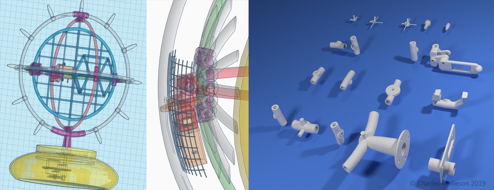
The gimbal assembly was created using aluminum tubing, which was bent to form sections of four concentric rings of the frame and outer, middle and inner rings of the gimbal. Each of the rings is driven by a ‘nano’ servo (as used in small radio-controlled models). While from an aesthetic perspective, the smallest available servos would be ideal, it was found that slightly larger servos were needed to provide sufficient torque and angular resolution to reliably actuate the gimble. Since the servos only rotate about a quarter of a revolution, gearing up by 4x, 2x and 4x was required to achieve the ranges of motion of the outer middle and inner rings, respectively (see Figure 2). Particular care was taken in the design of the servo mount and transmission for the middle ring, which is tightly constrained on both sides by the motion of the other two rings. Another tricky aspect was routing the power and control signal wires from the base up through the tubes and bearings to the two gimbal-mounted servos. As shown in Figure 5, the mounts, bearing and transmission housings were designed using an online CAD tool [9] and 3D printed in nylon, which was finished with metallic copper paint.
Two small brass counterweights are attached to the inner gimbal ring on the opposite side to the cube in order to balance the gimbal. These help avoid undesirable static loading of the servos and also add to the aesthetics. The cube and hour ticks were constructed from brass tubing. The cube is mounted at 45 degrees with respect to the plane of the inner gimbal ring to make it stand out from the plane while providing an edge for attachment rather than a single point. The video below shows the watch face and mechanical clock in operation.
Conclusion
The devised rotating cube clock is a form of computational art, technically motivated, yet aesthetically pleasing. There is a synergy between the practical considerations and the aesthetics of both incarnations of the clock: the modelling materials found convenient for constructing the physical clock lend themselves to the ‘steampunk’ aesthetic, while the hardware limitations of the watch lend themselves a ‘retro’ 3D graphics look.
While the optimization of the cube rotation is for a particular viewing position (i.e. head-on from a given distance), the time can still be read from it as long as the viewer is reasonably close to the assumed viewing direction. It is envisaged that the clock would be displayed in a ‘pigeon-hole’ type shelf, which would preclude significant deviation from the optimal viewing direction. The compact form-factor, low cost and ease of integration of RC servos make them an attractive choice for actuating the gimbal, however the RC servos’ standard internal control mechanism is not tuned for the relatively high inertial load of the gimbal assembly, resulting in occasional short-term oscillation in the gimbal position. Future work could investigate improving the smoothness of the gimbal motion.
References and Notes
- “Steampunk: A genre of science fiction that has a historical setting and typically features steam-powered machinery rather than advanced technology” Oxford University Press (OUP) https://www.lexico.com/definition/steampunk, retrieved 2020/01/20
- J.D. Foley, A. van Dam, S.K. Feiner, J.F. Hughes, and R.L Phillips Introduction to Computer Graphics. (Boston: Addison-Wesley, 1997) pp. 161-191.
- D. Eberly, “Euler Angle Formulas”, Geometric Tools, Redmond WA 98052 (March 2014) https://www.geometrictools.com/, retrieved 2020/01/20
- Wikipedia – Gyroscope, https://en.wikipedia.org/wiki/Gyroscope, retrieved 2020/01/20
- There is a small difference between the viewing optimization parameters of the virtual and physical incarnations of the cube clock: for the virtual version, in addition to the 3D rotation of the cube, a 1D forward-backward motion is allowed, ensuring that the absolute scale of the clock hands can be to be maintained exactly for all times of day, whereas in the physical version, a set viewer distance is assumed, meaning that a small amount of apparent scale change in the hands takes place.
- J. Nocedal, and S.J. Wright “Quasi-Newton Methods”. Numerical Optimization. (New York: Springer, 1999) pp. 192–221.
- Garmin Connect IQ SDK, https://developer.garmin.com/connect-iq/monkey-c/, retrieved 2020/01/20
- The Raspberry Pi Foundation, https://www.raspberrypi.org/, retrieved 2020/01/20
- Autodesk TinkerCAD, https://www.tinkercad.com/, retrieved 2020/01/20

Beautiful, really elegant. Or as they say in modern English ‘pretty slick, dude…’ Where can i buy one?
LikeLike